+7 499 245 55 68

The Welding gauge

* Upon requests when there is a need the TapiRUS can be delivered with an extended linear member  3 with a measuring length range of 0 ... 120 mm

description of the essential components 

The welding gauge consists of the main components which are:the fillet arm 2 and the linear member 3, on which the top High-Lo arm 4 with a taper gauge 5. 


The fillet arm 2, the linear member 3, and the top High-Lo arm 4 are fixed in the grooves by the rivets 6 ... 8. 

To position the welding gauge in a plane perpendicular to the surface which can be either flat or cylindrical, the pivots (9) are used. 

It is fixed on the base denoted by the digit 1 with the aid of the pivot arm rivet (10).

Zero position

Position the welding gauge on a flat surface; the fillet arm 2 and the taper gauge 5 must make contact with the surface.

Adjust the linear member 3 until the taper gauge 5 and the main gauge plate 1 are in contact. 

The grinding mark indicator E must coincide with the grinding mark denoted by “∞” of the scale diameters D; K, H, W in the zero position.


Basic measurements

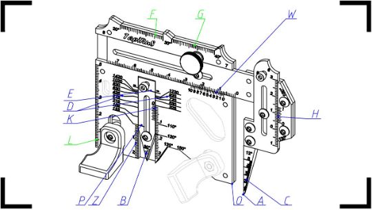
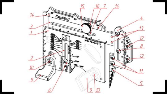
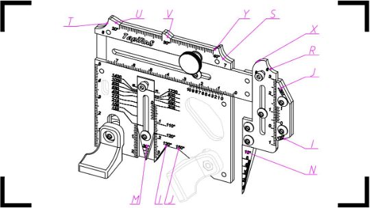
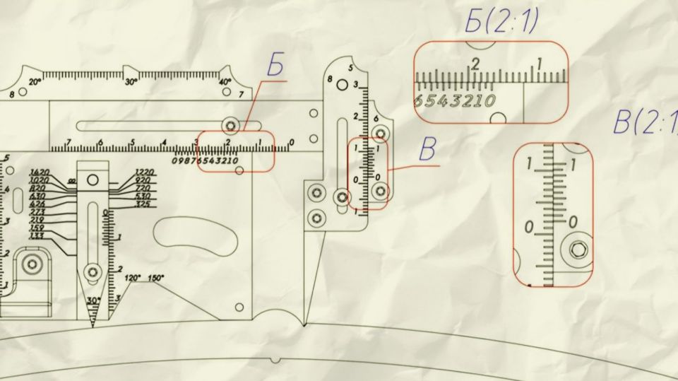
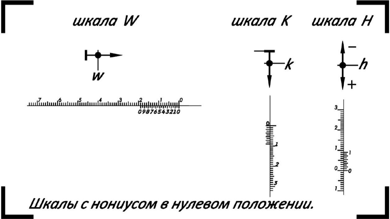
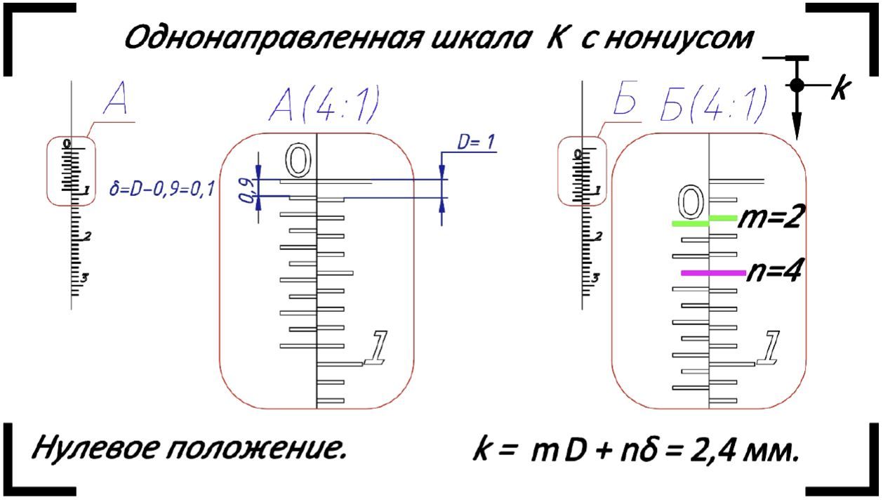
The fillet arm 2 allows you to measure the root gaps using the scale E. Leg lengths and grooves on flat surfaces are measured by the vertical unidirectional scale D. 

Position the taper gauge 5 along the normal to the surface for cylindrical objects when measuring the parameters of longitudinal welds. 

Lastly, the fillet arm 2 should be extended out from the base (1), and the position of the grinding mark indicator J should correspond to the inspected pipe diameter of [133 ... 1420] mm. 

The position of the fillet arm 2 should be fixed by tightening the filletv arm rivet. The taper gauge 5 serves as the main measuring element and it is made of hardened steel. 

However, to prevent its premature wear, raise it up before loosening it by adjusting the Top High-Lo rivet 8. Lower it until it makes contact with the surface of the inspected object at the measurement point. The bi-directional scale C on the top High-Lo arm 4 allows taking measurements with the taper gauge 5along the normal to the surface. 

Measurement of linear dimensions on a controlled surface or on a tangent to it is carried out on a horizontal scale B located on the the linear member 3, after it makes contact with the taper gauge 5at the point of measurement.Bar adjustiments are regulated and altered by the screw denoted by 7. 

To fix the linear member 3 in the measuring position, both the the clamping screw 15 and a linear member washer 16 are used, with which the strap 3 is pressed against the base 1

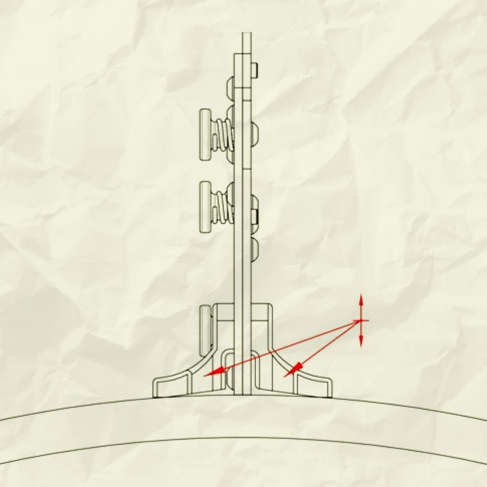
Smoothness transition assessment from the weld to the metal base is made by calibrators denoted by the letter N and O. It is also allowed to dissemble the parts of the welding gauge by removing the rivets 6 ... 8 and the pivot 9.

Taking the measurement results from Vernier scales

General Information

The welding gauge has three scales with a nonius.The use of the Vernier allows an increment of accuracy of the readings on the scales K, H and W as illustrated by the Figure 6 below . 

The principle of the vernus is based on the following. The accuracy of visual interpolation of the position of the pointer between the divisions of the scale is low and by approximation it is about 1/3 of each division. However, the eye can record it with high accuracy from the exact point of coincidence of two the images. 

An error in recording such a coincidences is a fraction of the thickness of the grinding marks, which, is significantly less than the aforementioned 1/3 of the distance between the grinding marks. The nonius also allows you to obtain the information about the position of the pointer between the divisions of the scales at the exact point of coincidence of two marks.

Nonius is a moving scale www.tapirus.info 10 из 59 associated with a pointer that slides along the main scale. The pointer simultaneously works as the zero position of the vernier scale. The divisions on the vernier scale are plotted as follows. 

Vernier Accuracy Selected: δ = D/N, where : D – division scale of the main scale (for scales K, H и W = 1mm) N – natural number (10 for scale K, H and 20 for sale W). 

 If we combine the zero vernier with one of the divisions of the main scale, then the first grinding mark of the vernier is applied so that it lags the next mark of the scale by δ, the second by 2δ, the nth by nδ. 

The last Nth grinding mark of the vernus again coincides with one of the figures on the main scale.

If during the measurement process the scale pointer is shifted to δ, there will be a coincidence on the first nonius marks n = 1. 

Thus, if the measurement of the nth mark of the nonius gave a match, then the scale pointer is offset by nδ from the last division of the main scale passed. 

The full measurement result e.g the length L is found by summing the values corresponding to this last division of the main scale (m) and the offset nδ: L = mD + nδ.

TAKING MEASUREMENT RESULTS FROM A ONE-DIRECTIONAL SCALE K

Scale Pitch D = 1 mm; δ = 0,1 мм. Range of measurements [0…23] mm.

TAKING MEASUREMENT RESULTS FROM A ONE-DIRECTIONAL SCALE W

Scale Pitch D = 1 mm; δ = 0,05 mm.Range of measurements [0…55] mm.

TAKING MEASUREMENT RESULTS FROM A ONE-DIRECTIONAL SCALE N

Scale Pitch D = 1mm; δ = 0,1 mm. Range of measurement scales not more than [-6…20] mm. 

The measurement range when the taper gauge 5 is moved down is conditionally selected positive from the interval of [0 ... 20] mm. 

The number of integers in mm is counted from the zero mark of the main scale upwards, and the number of tenths from the zero mark of the nonius is taken upwards. 

The measuring range when the taper gauge 5 is shifted up, respectively, is conditionally selected negative form the interval of [-6 ... 0] mm. 

The number of integers in mm is counted downwards from the zero mark of the main scale, and the number of tenths, respectively, from the mark of the nonius 1 is counted downwards .